.jpeg)
Present: M. Blaszkiewicz, L. Felsberger, B. Panev
In the meeting, there were three models presented: baseline model (closest to current configuration), re-routing model (where certain IC is duplicated to remove a single point of failure) and FPA duplicated via SPA loop model (where FPA output is connected to the SPA input to double safety).
The use of triplicated logic within FPGA for protection against R2E (Radiation to Electronics) events was reiterated, with voting on top of it.
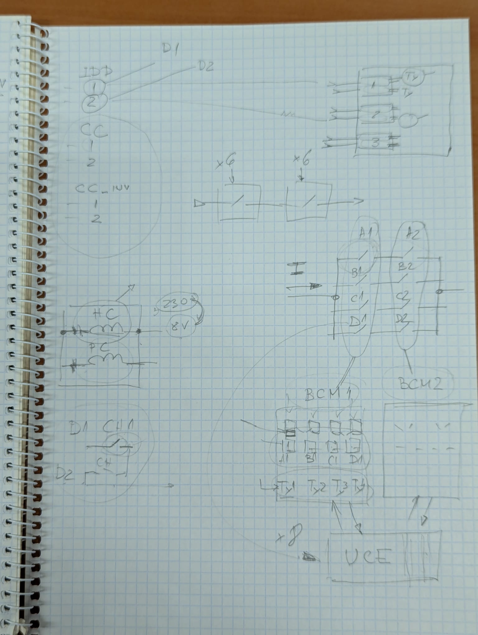
As for the driver board, there will be most likely 9 channels for 600A. There are new HL switches: 600A & 2kA, where optical fibres trigger, there are two fibers per switch into pulse train thyristor firing unit and which consist of ICC and CC parts. They are made with optocouplers.
For 13kA, there will be 8 switches in 4 parallel branches. Each 4 switch (grouped by the fact of being first or second switch in branch) will be controlled by a Breaker Control Module (BCM) 1 or 2. UEEC controls both. There are two coils in swtiches (one to keep it closed, the other one for opening - pulse coil).
In BCM, a relay is for holding and thyristor for opening. When opening - firing all (but only opening one counts); interface with the driver will be the same as before - two relays in series to switch.
Single point of failure; connecting FPA output as SPA input is tricky for 13kA (optocouplers space in "voltage budget"), for 600A source is EPC (same for vacuum switches). The idea will be consulted with colleagues.