Univ. EE Controls reliability studies - progress meetings 2024

Europe/Zurich
30/3-023 (CERN)

30/3-023

CERN

12
Show room on map
    • 09:30 10:30
      Univ. EE Controls reliability studies - progress meeting #1 1h 30/3-023

      30/3-023

      CERN

      12
      Show room on map
      • State of the Project (Bozhidar)
        • Recap of design philosophy
          • The idea is to have a single electronics chassis to serve all energy extraction types
          • The chassis consists of a motherboard connected to a set of cards (functional diagram in slides in indico link) on one side and to a back-panel on the other side.
          • All hardware except the back-panel (different connectors depending on EE HW, passive components only) will be identical
          • The firmware of the controls cards will be changed depending on the EE HW
        • Recap of project progress
          • A prototype for the vacuum switches has been made
          • A pre-series of ten boards has been launched for general testing and radiation testing in CHARM
          • The series design should be finalized in September 24
            • Small changes are foreseen to increase test-ability of PCBs (with spring contact based tester)
          • Main production should be launched in Jan/Feb next year
        • à outcome of reliability study should be ready for design finalization in September 24
      • State of the reliability study (Lukas)
        • Overview presented - https://indico.cern.ch/event/1380711/contributions/5815765/attachments/2800642/4885911/slides%20and%20notes%20post%20meeting.pdf
        • What was done
          • Functional diagram
          • Top-level FMECA
          • Simulation model for most critical function: drive switch opening upon opening of FPA loop
        • What was observed
          • The most critical function requires a blind failure rate of approximately a few hundred FITS per redundant path. It should be compared against a component based prediction to ensure that requirements are fulfilled.
          • The behaviour of the EE controls under power loss for the vacuum switches should be investigated closer, as the opening needs to be actively driven
          • Other possible critical interlocks received should be inspected closer
      • Next steps
        • To cover the mentioned observations, it was considered best to analyse them specifically for the situation of the vacuum switches as they are considered most critical. Based on the outcome of the model for the vacuum switches, it will be checked whether there are other more critical use-cases (e.g. electromagnetic switches). The aim is to have results for the vacuum switch scenario by summer.
        • Action: Bozhidar will send the latest design files
        • Action: Milosz and Lukas will use the design files to prepare component prediction templates
        • Action: Bozhidar will provide a more detailed representation of the critical paths for driving the switch opening of the vacuum switches under a critical interlock (opening of FPA loop, loss of power, possible other external interlock)
        • Action: Milosz and Lukas will update the simulation model accordingly
          • Also considering comments made by Bozhidar during the meeting
            • Additional fan-out of signals
            • Monitoring of voltage presence/power supply situation


    • 15:30 16:30
      Univ. EE Controls reliability studies - progress meeting #2 1h 30/2-005

      30/2-005

      CERN

      15
      Show room on map

      Failure rate prediction summary, failure modes apportionment, encountered issues, follow-up questions; deciding on FMECA approach.

      Speaker: Milosz Robert Blaszkiewicz (CERN)

      Univ. EE Controls Reliability Study - 2

      Present: M. Blaszkiewicz, L. Felsberger, B. Panev

      Minutes

      The meeting's objective was to present the results of the failure rate prediction step for the EE UC boards and decide on the next step - the end-effects assignment. It started by LF recounting the state of the study and completed work. Then, as shown in the slides, an introduction of the study methodology proceeded, followed by results of the failure prediction step for three EEUC boards: Controls, Driver, FPA SPA. 

      The next part was a summary of the hybrid MC simulations. They will be updated accordingly, following the issues discussed as well as new FITs estimations only with relevant components, after getting the list of those from BP. 

      A number of additional observations has been made throughout the presentation:

      • Through holes, fiducial targets - confirmed that can be left at 0 FITs; mostly used when card is taken out of the tunnel to a tester.
      • TVS diodes are protecting the FPGA; that one gets voltages of 1.2V, 2.2V and 3.3V. 
      • UBS Interface in the Controls Board will be used only for diagnostics when someone obtains access. Not to be used during operation.
      • The critical path is supposed to be composed of the FPGA, Powering, some logic gates. LEDs are not critical, and buttons will be largely removed.
      • EEPROM will be used to keep track of information about the PCB, its unique coding, where it is, has it been used, etc. Provides information through a communication card to the outside. 
      • Fuses are used for protection against radiation deterioration - are much higher than rated current.
      • According to BP, regulators - all components are tested in the BECO Radiation to Electronics. They will be tested in CHARM as well.
      • Switches will be used only for configuration; still, some of them will be critical. All switches in PCBs here are DIP.
      • Push buttons in FPA SPA will stay.
      • There are 4 optocouplers - 2 going to CNTL 1, 2 going to CNTL 2.
      • Interlock board is reporting to the control cards. 
        • CNTL to FSPA rupture the FPA loop.
      • CERN bPOL12V - raised the point about recommendations, BP said they will try to go below 12V.
      • Tantalum derating.  

      Actions

      1. Send a list of components to BP, add interlock card.
      2. BP will prepare a list of components relevant to the critical failure path - only in the most critical configuration.
      3. 600A type circutis - to be checked if EE opens the FPA loop.
    • 14:00 15:30
      Univ. EE Controls reliability studies - progress meeting #3 1h 30m 30/3-023

      30/3-023

      CERN

      12
      Show room on map

      Understanding the criticality of components and pages in the following boards: Interlock, Controller, FPA/SPA and Driver.

      Univ. EE Controls Reliability Study - 3

      Present: M. Blaszkiewicz, L. Felsberger, B. Panev

      Minutes

      Design for each board has been analysed separately, here are the highlights gathered:

      FPA/SPA

      Critical pages: Connectors, Interlock Loop A, (Interlock Loop B too, but not used).

        • Also has push buttons & remote connection.
        • Makes multiple connections besides FPA/SPA.
        • Also creates commands:
          • open, close, reset,
          • fpa, spa goes separately.
        • Opening the loop also done.

      Interlock

      Critical pages: Buffers, Connectors, Interlock channel (x15).

          • How many ones are critical depends on the EE system:
            • vacuum - 15 critical,
            • 600a - ?.

      Driver

      Critical pages: all aside from power supply and P1 (+ lower side of the page).

        • open --> or gate
        • close --> and gate, also done at the level of two driver boards (by routing in series)
        • dip switch - selects OC or relay (only for ch1 and ch2)
        • each system uses 7-8 channels, 13 ka maybe all
        • active opening of drive for vacuum switches --> have to immediately open them --> is on the interlock card --> sensing on the switch input voltage side and chassis
          • capacitors monitored

      Control

      Critical pages: FPGA Banks (x2), FPGA, Backplane Connector P1, P2, P3.

        • Reset FPGA will also open switches beforehand.
        • Closing of switches is not allowed during reset.
        • When FPGA clock stops, switches are opened.
        • Very little of FPGA capabilities used.
        • Undefined voltage - not clear.
        • ID part is for card only - not for configuration of fpga - not critical.
        • Multiplexer - not critical - jtag, usb, programming interface.
        • P6 (or P5): possibly to have CNTL card cross-communication.
          • also to notice in idle when one card is missing.
        • P4 - analogue measurements - not an interlock
          • interlock is thermostat - in parallel.
        • USB - debugging and programming only for closing switches


      Timeline

      February, March - design office for series production

      Actions

      1. Establishing a failure rate for critical components only.
    • 16:00 17:00
      Univ. EE Controls reliability studies - progress meeting #4 1h 30/3-023

      30/3-023

      CERN

      12
      Show room on map

      Results of more detailed simulations

      Speaker: Milosz Robert Blaszkiewicz (CERN)

      Univ. EE Controls Reliability Study - 4

      Present: M. Blaszkiewicz, L. Felsberger, B. Panev

      Minutes

      In the meeting, there were three models presented: baseline model (closest to current configuration), re-routing model (where certain IC is duplicated to remove a single point of failure) and FPA duplicated via SPA loop model (where FPA output is connected to the SPA input to double safety).

      The use of triplicated logic within FPGA for protection against R2E (Radiation to Electronics) events was reiterated, with voting on top of it.

      Driver board

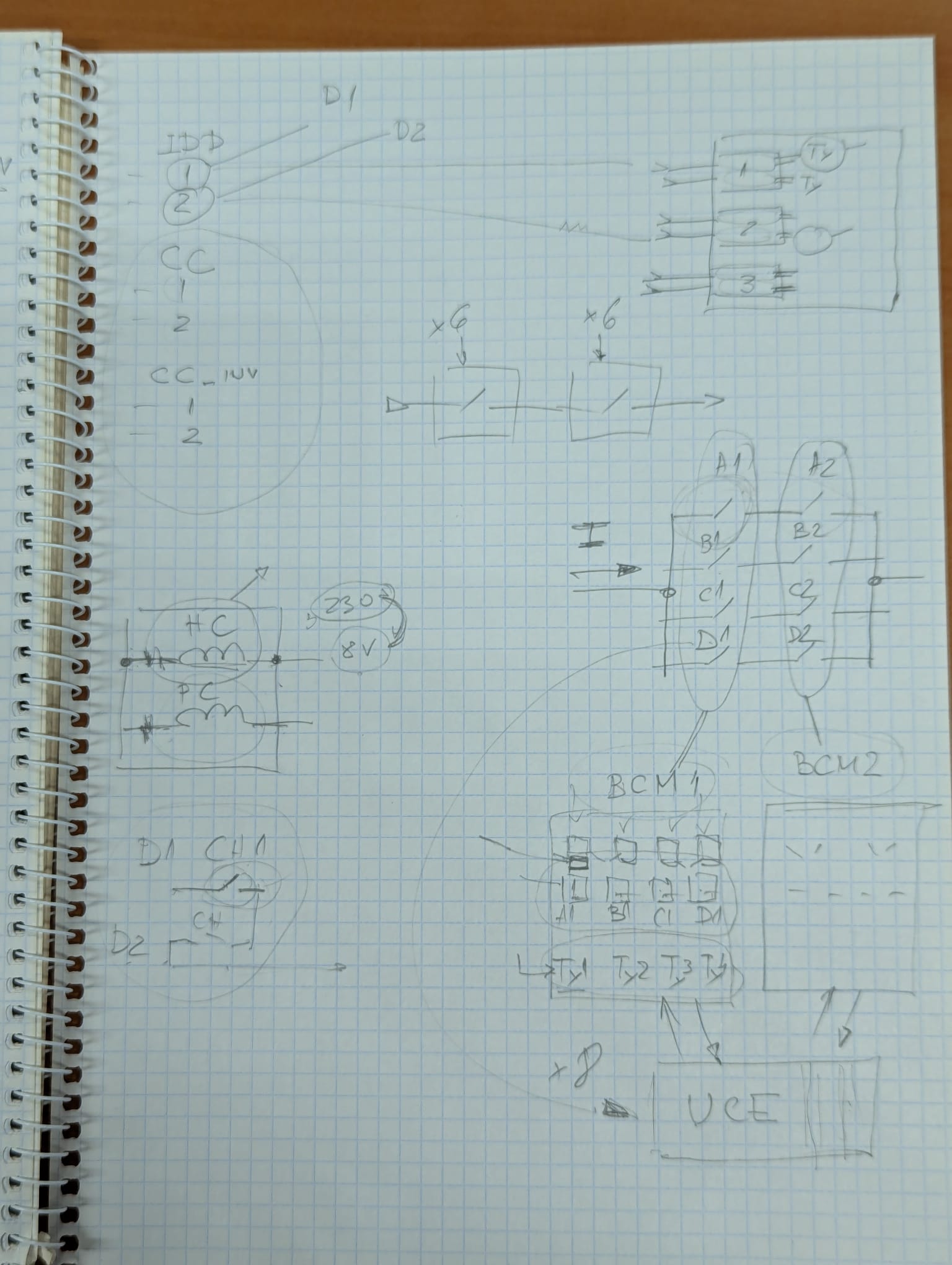
      As for the driver board, there will be most likely 9 channels for 600A. There are new HL switches: 600A & 2kA, where optical fibres trigger, there are two fibers per switch into pulse train thyristor firing unit and which consist of ICC and CC parts. They are made with optocouplers.

      For 13kA, there will be 8 switches in 4 parallel branches. Each 4 switch (grouped by the fact of being first or second switch in branch) will be controlled by a Breaker Control Module (BCM) 1 or 2. UEEC controls both. There are two coils in swtiches (one to keep it closed, the other one for opening - pulse coil).

      In BCM, a relay is for holding and thyristor for opening. When opening - firing all (but only opening one counts); interface with the driver will be the same as before - two relays in series to switch.

      FPA/SPA card

      Single point of failure; connecting FPA output as SPA input is tricky for 13kA (optocouplers space in "voltage budget"), for 600A source is EPC (same for vacuum switches). The idea will be consulted with colleagues.

      Actions

      1. Updates to the failure moeds and rates - look at the input stuck high for the critical component in the interlock board too.
      2. Make the driver side more generic.
      3. Create a model for the critical interlocks. 
      4. Follow-up the FPA through SPA loop reduntancy. 

    • 14:00 15:00
      Univ. EE Controls reliability studies - progress meeting #5 1h 30/3-023

      30/3-023

      CERN

      12
      Show room on map

      Discussion of another model iteration

      Speaker: Milosz Robert Blaszkiewicz (CERN)

      Univ. EE Controls Reliability Study - 5

      Present: M. Blaszkiewicz, L. Felsberger, B. Panev

      Minutes

      BP provided feedback from the previous meeting - after discussions with colleagues, it was decieded to separate two redundant path signals going previously through one component (IC22) at the end of the chain in FPA/SPA card. The new approach is to have main singals in one (IC22) while their redundant versions (R) in the other (IC46). It is possible as there will be some other changes implemented.

      Interlock

      BP highlighted that IC8 is a high impedance element and therefore should never experience input short (to high). It was also reiterated that there was more than ten years of operation in R2E test which already provided some insights.

      The plan is to have yearly checks of interlocks, but for vacuum switches it may be every two years. 600A switches though - only LS.

      It was also mentioned that all critical interlocks will be locked redundantly.

      Most switches fail safe without interlocks, vacuum switches - have to be driven, therefore: they rely more on interlocks. 

      Actions

      1. Explore options for a more detailed model with interlocks and/or provide other estimation for that case.  
    • 14:00 15:00
      Univ. EE Controls reliability studies - progress meeting #6 1h 30/3-023

      30/3-023

      CERN

      12
      Show room on map

      Models of the system in two scenarios: with FSPA card and with Interlock card

      Speaker: Milosz Robert Blaszkiewicz (CERN)

      Univ. EE Controls Reliability Study - 6

      Present: M. Blaszkiewicz, L. Felsberger, B. Panev

      Minutes

      The meeting focused on two models of the energy extraction universal controls: one for the scenarios in which it is activated via FSPA card and the other one for scenarios where opening is triggered via Interlock card. The basic assumptions for the cards were reiterated - which led to identifying a missing element: for vacuum switches, the driver cards need to activate all three channels. This is so, because the channels conenct to three parts of the energy extraction: the drive of the switch itself, as well as the counter current (in both directions).

      It was agreed that we will share the report as soon as it is ready. In addition, BP suggested that the report could be presented in the TE-MPE TM meeting in some time.

      Actions

      1. Update the driver card model to account for vacuum switches where all 3 channels are needed to properly activate the system. 
      2. Create a report summarizing the study.