Choose timezone
Your profile timezone:
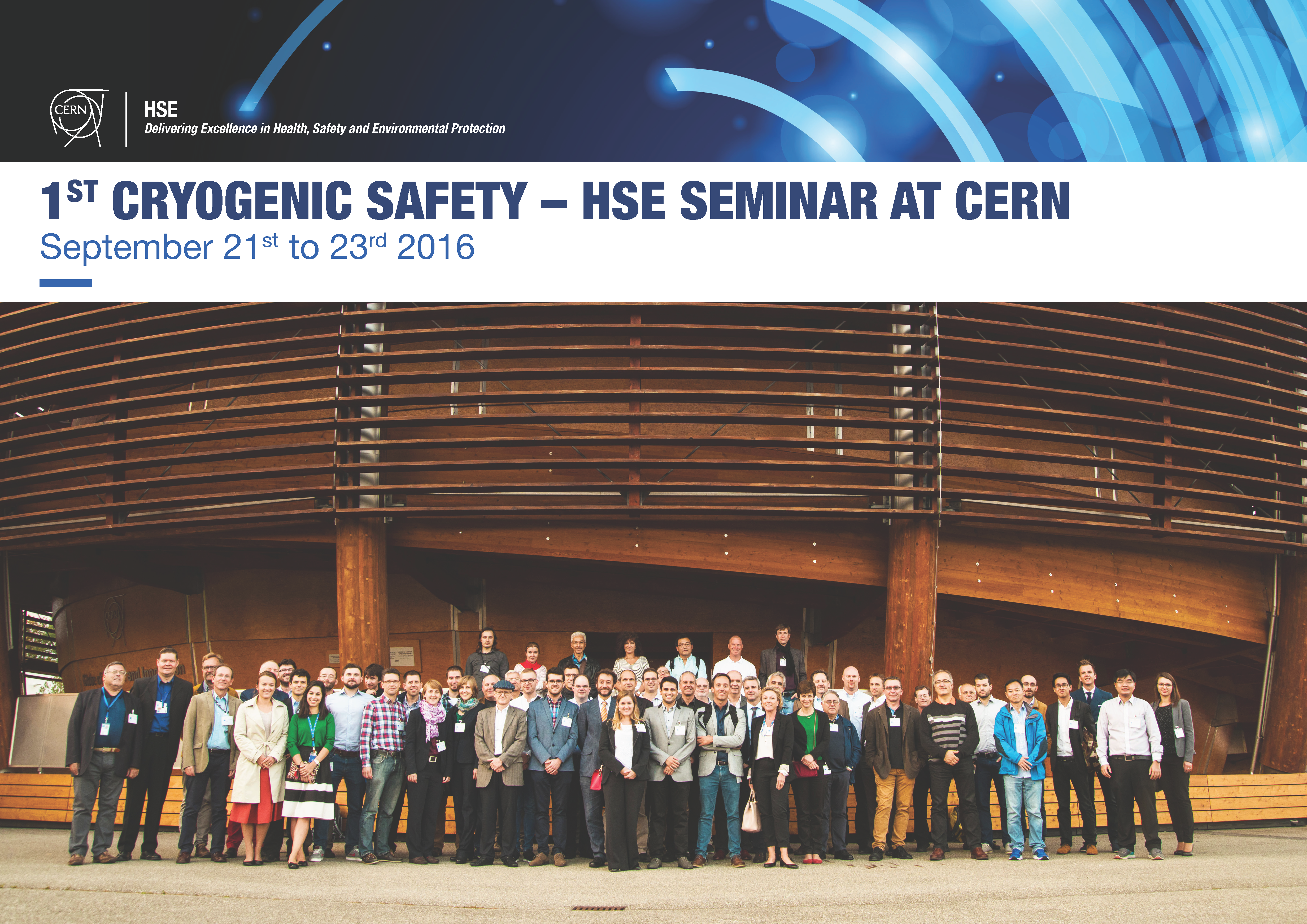
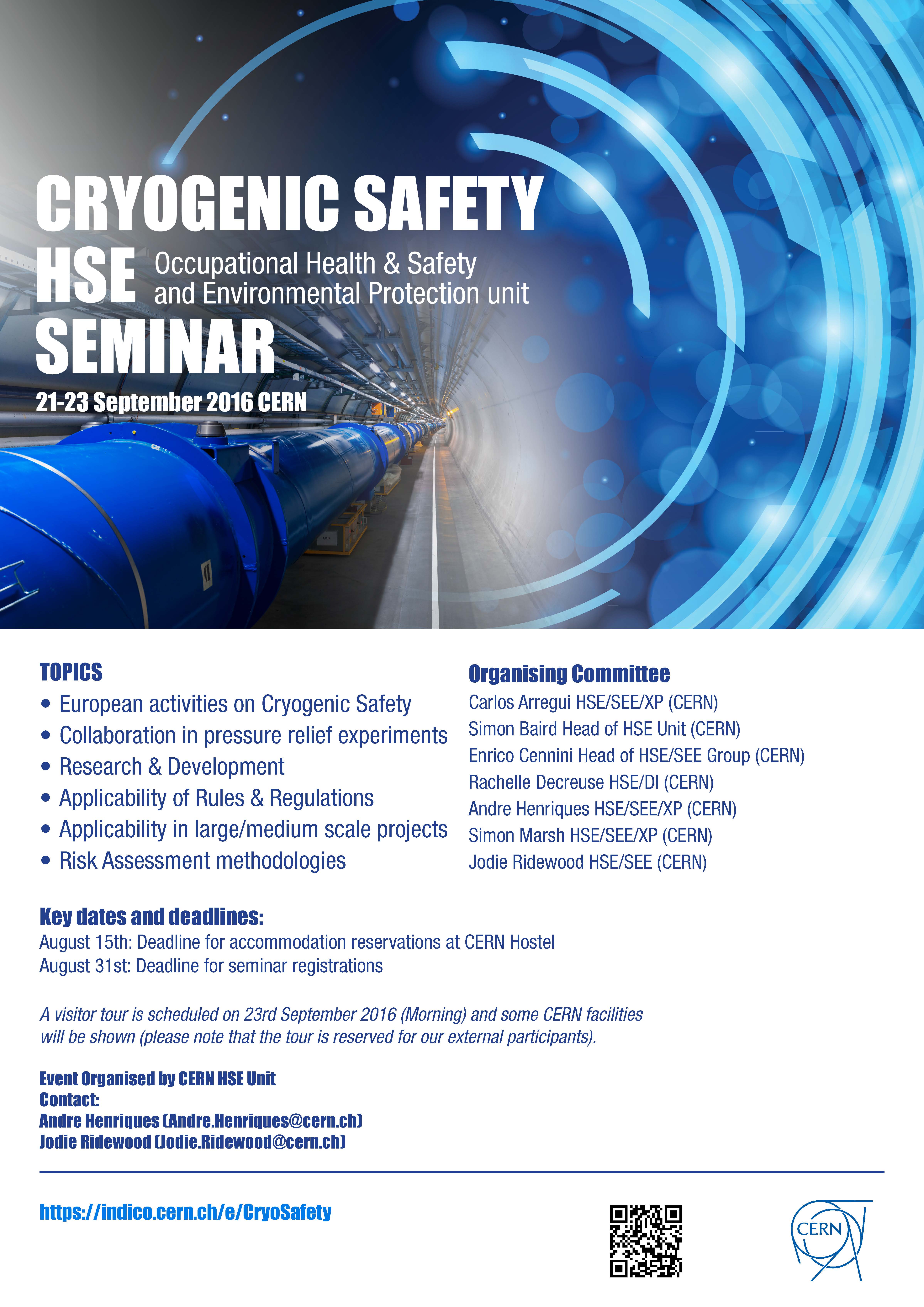
The first Cryogenic Safety seminar, organised by CERN HSE Unit will take place from 21-23 September 2016 at CERN.
The idea of this seminar is to share knowledge among different institutes and industrial partners that are willing to discuss various topics in the cryogenic safety domain.
A visitor tour for Cryogenic Safety Seminar is scheduled on 23rd September 2016 (Morning) and some CERN facilities will be shown (please note that the tour is reserved for our external participants).
The name as indicated in the registration form will be used on your participant badge that will be distributed upon your arrival at CERN.
Key dates and deadlines:
- August 15th: Deadline for accommodation reservations at CERN Hostel - NB: ALL HOSTEL RESERVATIONS NOW FULL. PLEASE SEE OTHER POSSIBILITIES IN THE ACCOMMODATION TAB.
- August 31st: Deadline for seminar registrations
Organising Committee:
Carlos Arregui HSE/SEE/XP (CERN)
Simon Baird - Head of HSE Unit (CERN)
Enrico Cennini - Head of HSE/SEE Group (CERN)
Rachelle Decreuse HSE/DI (CERN)
Andre Henriques - HSE/SEE/XP (CERN)
Simon Marsh HSE/SEE/XP (CERN)
Jodie Ridewood HSE/SEE (CERN)
Administrative Support: Jodie.Ridewood@cern.ch
Welcome Speech by Simon Baird, Head of HSE (Occupational Health & Safety and Environmental Protection) Unit of CERN
Introductory speech by Andre Henriques, on behalf of the organising committee, outlining the programme and motivation of the event.
This talk gives a general overview on the challenges of designing safety units for liquid helium cryostats with regard to existing industry standards. It reviews the work of a national working group that published the technical guideline DIN SPEC 4683 in April 2015, which is dedicated to the particular conditions in liquid helium cryostats. Based on both this guideline and equivalent documents from e.g. CEA, CERN, a working group is being formed at the European Committee for Standardization, associated to CEN/TC 268, which will work on a European standard on safety of liquid helium cryostats. The actual status and the schedule of this project are presented.
With Safety being a top priority of CERN’s general policy, the Organisation defines and implements a Policy that sets out the general principles governing Safety at CERN. To the end of the attainment of said Safety objectives, the organic units (owners/users of the equipment) are assigned the responsibility for the implementation of the CERN Safety Policy at all levels of the organization, whereas the Health and Safety and Environmental Protection Unit (HSE) has the role of providing assistance for the implementation of the Safety Policy, and a monitoring role related to the implementation of continuous improvement of Safety, compliance with the Safety Rules and the handling of emergency situations.
This talk will elaborate on the roles, responsibilities and organisational structure of the different stakeholders within the Organization with regards to Safety, and in particular to cryogenic safety. The roles of actors of particular importance such as the Cryogenic Safety Officers (CSOs) and the Cryogenic Safety experts in the HSE unit, as well as the Safety validation process for projects involving cryogenic equipment will be thoroughly explained.
The dimensioning of cryogenic safety relief devices requires detailed knowledge on the process dynamics following the quench of superconducting magnets or the break of the insulating vacuum. In established standards and design codes, the sizing of cryogenic safety relief devices is based on constant (maximum) heat flux data, which potentially leads to oversized safety relief devices. Beside the implications on cost, space and helium leakage, oversized safety valves often lead to unstable operation during discharge with reduced relief flow capacity due to chattering and pumping. Dynamic models improve the understanding of dependences and design parameters for such devices.
This talk discusses a differential equation model for all time-dependent sub-processes in the case of a breaking insulating vacuum, and compares the results to experimental data from the test facility PICARD.
The presented work focuses on the risk analysis and the consequences of the unexpected leak to the tunnel of cryogenics gases. Formation of the gas mixture and its propagation along tunnels is an important issue for the safe operation of cryogenic machines, including superconducting accelerators or free electron lasers. As the cryogenics gas the helium and argon will be considered. A minimal numerical model will be presented and discussed. Series of numerical results related to emergency helium relief to the CERN tunnel and related to unexpected leak of the argon to an underground tunnel, will be shown. The numerical results will show temperature distribution, oxygen deficiency and gas cloud propagation in function of intensity of the leak and intensity of the ventilation.
The test facility PICARD, which stands for Pressure Increase in Cryostats and Analysis of Relief Devices, has been designed, constructed and commissioned for cryogenic safety experiments. With a cryogenic liquid volume of 100 liter, a nominal design pressure of PN16 and helium relief flow rates up to 4 kg/s, the test facility allows the systematic investigation of hazardous incidents in cryostats under realistic conditions.
PICARD aims to study the process dynamics of heat fluxes and relief flow rates during cryogenic safety incidents in the frame of a R&D collaboration between KIT and CERN. This involves venting of the insulating vacuum with air or gaseous nitrogen using different venting hole diameters, thermal insulations, liquid levels and the set pressures. A further focus is on the occurrence and the implications of two-phase flow during expansion, and on the operating characteristics of safety relief devices.
In this contribution, the test facility PICARD is presented. Exemplary results of venting experiments with regard to the pressure increase and heat flux densities are discussed and compared to literature data.
To perform the sizing of a safety device, the first step is the estimation of the heat flux arriving on the surfaces of the component to protect. The only reliable way to know this parameter is to perform experiments. Different tests have been done in the past by different teams but never with components filled with helium and discharging in supercritical state. CEA/SBT has in operation a test facility to quantify the heat flux on a helium tank for this kind of application in case of “loss of vacuum”. The preliminary results will be presented versus the number of layers of MLI and the fluid responsible of the loss of vacuum.
The selection process for size in safety equipment for cold vessels or process pipes in cryogenic systems should take into consideration the incidental ventilation of the vacuum vessel with atmospheric air. In this case, a significant heat input toward the cold elements of the system can be expected. A number of experimental investigations have been done for the elements at liquid helium temperature which have been covered with 10 layers of MLI. The typical values of the heat flux were measured in a range of 3.7 to 5.0 kW/m2 of the element surface. The helium temperature parts are typically surrounded by thermal shields that are kept in a temperature range of 50-80K. On the external side, the thermal shields are covered with 30-40 layers of MLI while on the internal side, the shields are bare. The theoretical calculations of heat flux to the thermal shield, with respect to the possibility of air condensation and freezing on the bare side of the thermal shield, show that the heat flux to the thermal shield can be extremely large. A review of the available literature shows no experimental data in this area of interest.
Another issue can be found in the unknown ratio of inflowing air, which is deposited on the liquid helium temperature surface, to the air which is deposited on the thermal shield. This would be important if the ratio of the expected cross section area of a hole in the vacuum vessel to the surface area of the cold elements is found to be relatively small.
This talk will discuss the abovementioned problems. A WUST cryostat designed to allow the determination of heat flux to the bare surface of the thermal shield, as well as test methodology, will also be presented.
Restaurant 1
The 27-km circumference LHC underground tunnel is a confined space in which the helium-cooled LHC magnets are installed. The vacuum enclosures of the superconducting magnets are protected by over-pressure safety relief devices that open whenever cold helium escapes either from the magnet cold enclosure or from the helium supply headers, into this vacuum space. Based on scale model studies a 3-m long no stay zone around these devices is defined to protect the personnel against cold burns or asphyxia caused by such an eventual helium release. To validate recent simulations real life mock-up tests have been performed inside the LHC confined space, releasing helium flow rates of 1 kg/s, 0.3 kg/s and 0.1 kg/s. For each test, up to 1000 liters of liquid helium were released under standard operational tunnel conditions. The data recorded include oxygen concentration, temperature and flow speed measurements, and video footage permit to assess qualitatively the visibility. These measurements were made in the up- and downstream directions, with respect to the ventilation flow, of the spill point in the LHC tunnel.
Tests conducted in 2013/4 demonstrated that a small, residual risk to expose personnel to a helium spill exists in the LHC. Helium spills with a mass flow of less than 100 g s^-1 could be caused by workers accidentally damaging sensitive equipment in the cryogenic distribution system, such as instrumentation feedthroughs.
In order to control this risk, a cryogenic risk assessment for all works taking place in the vicinity of such sensitive equipment is mandatory. The risk assessment and its recommendations are approved by the hierarchy and the complex manager before work can start.
After introducing the risk assessment procedure, I will give some feedback on its implementation and present status.
Superconducting magnets are supplied with a few kA of electric current and can store a large amount of energy. Therefore, cryogenic systems which are comprised of such magnets are subject to the risk of fast energy discharge from the magnets themselves in the form of an electric arc. The arcing can be a result of failure in the insulation of an electric circuit or in the connection between the magnet and its current lead. During the discharge, energy can be partially dissipated into the cryogen and partially into the cryogenic system metallic structure. The part of the energy that is transferred to the metallic structure will strongly heat up the metal surface, which can lead to material burning. In this case, the cryogen will flow through the perforation to the insulation vacuum space, which can trigger a rapid increase in pressure in the vacuum enclosure. However, the discharged energy that has been stored in the cryogen also causes a rapid increase in cryogenic pressure. Hence, the proper estimation of the amount of electric arc energy stored in the cryogen and in the metallic structure of the cryogenic system is a crucial issue in the sizing of the safety valves for the cryogenic system cold circuits and its vacuum vessel.
This talk will discuss issues concerning the conditions which result in electric arcing. This will include a theoretical approach in the determination of the electric arc energy discharge dynamics as well as offer an approach in the estimation of the amount of energy dissipation into the cryogen and the metallic structure of the cryogenic system. Details of a WUST cryogenic set-up for testing the energy discharge in the form of an electric arc and the test methodology will also be presented.
The European Spallation Source (ESS) is building a linear accelerator (linac) aiming at delivering a 2 GeV proton beam on a tungsten target wheel at 5 MW nominal power. The entire accelerator will be housed in an underground tunnel and will be fully operational by 2023.
The superconducting section of the linac is composed of 21 High Beta cryomodules, 9 Medium Beta cryomodules and 13 Spoke cryomodules, as well as a Cryogenic Distribution System (CDS) that will be provided with liquid helium. A total of 146 superconducting radio frequency (SRF) cavities operating at 2 K will be housed in those cryomodules. Additionally, cryogenic fluids will also be used for the cold hydrogen moderator surrounding the target as well as for several neutron instruments. In order to achieve a proper cooling, different facilities are being built to house the future cryogenic installation and therefore will be subject to Oxygen Deficiency Hazard (ODH).
In order to address cryogenic safety issues ESS wide, a long-term strategy has been prepared based on the selection of calculation models, the implementation of an ODH safety guideline as well as the identification of control measures.
At this early stage, some preliminary ODH assessments have been carried out in various areas such as the accelerator tunnel, the compressor building and some laboratories using simple calculation models as well as Computational Fluid Dynamics (CFD) simulations.
The presentation will provide an overview of the ODH concept at ESS, examples of safety studies, results and lessons learnt from CFD simulations performed in the accelerator tunnel and finally some upcoming activities.
Compressed and liquified gases are used at many places at CERN. If they are introduced to the atmosphere, they can present an oxygen deficiency hazard (ODH) and lead to reduced abilities, unconsciousness or even death. The CERN method for ODH risk assessments is done on a case-by-case basis as each situation is unique. It is crucial to make sure the personnel can evacuate safely in case of an ODH situation.
My talk will explain human reactions to reduced oxygen levels and I will give some practical examples on how one can assess and control the hazards from a possible oxygen deficient atmosphere. Some real accidents involving oxygen deficiency will also be mentioned.
The electric light bulb has been called the most important invention since man-made fire, and Oren Harari is famously quoted as saying that it “did not come about from continuous improvement of the candle”. The modern lightbulb is however the result of 140 years of innovative work and continuous improvements on Edison’s original device. In today’s world, we acknowledge the enormous potential of academic research to produce both disruptive innovations and continuous technological improvements. Maximising the likelihood that they make it from the lab and into society is the raison d’être for CERN’s Knowledge Transfer Group. It is well recognised that research provides a significant driving force for enhancing economic growth and societal welfare. And for academics, knowledge transfer can be a way of gaining new perspectives on possible directions and approaches for research.
The Knowledge Transfer group at CERN aims to engage with leaders in science, technology and industry in order to create new opportunities for the transfer of CERN's technology and know-how. The ultimate goal is to accelerate innovation and maximise the global positive impact of CERN on society. This is done by promoting and transferring CERN's technological and human capital. The group works together with CERN technical departments to help researchers realise the potential of their ideas and innovations and actively seeks collaboration and partnerships beyond the domain of high energy physics.
Safety standards and best practices do exist in the field of cryogenics but, as in most domains, they are generally inserted in a few ‘envelope’ cases commonly used in the industry, whereas applicability to the particularity of research facilities are not fully tailored to its needs. The main objective in these cases is to find a harmonised approach, based on lessons learnt and scientific knowledge.
The Kryolize Project was created in order to produce tools with a harmonized approach to size pressure relief devices for cryogenic applications. In view of disseminating such tools to other institutes and industrial partners, the project was submitted to CERN’s KT Fund committee.
This talk will focus on the process and deliverables of the KT-Funded Kryolize project, including the method on how to cope with the sizing of pressure relief devices and the R&D collaboration agreement between CERN and Karlsruhe Institute of Technology for an experimental programme.
Kryolize is a novel software tool to a harmonized approch for sizing the minimum discharge area of safety devices for cryogenic installations. This talk will give an exclusive glimpse behind the scenes how a standard compliant software containing the latest results of research in the field of cryogenics at CERN can be developed. Starting from a collection of formulas the new software tool needs to fulfill certain requirements to allow a wide dissemination not only across the scientific community but also for the industrial sector, thus providing solid core development as well as a user friendly interface. This includes the optimization of the program flow as well as the development and efficient implementation of sophisticated approximation algorithms for a time saving and effortless user experience.
To avoid mistakes during the calculation, CEA/SBT has decided to write a software that take into account all the situations it is possible to encountered (subcritical state, supercritical state, …). The goal is to permit to the engineer in charge of a cryostat manufacturing to perform this calculation; he is the only person able to do the accidental analysis which is fundamental for the sizing of the safety device. The software performed will be presented.
Visit the exhibition "Universe of Particles" at the Globe:
http://visits.web.cern.ch/exhibitions/universe-particles
http://visits.web.cern.ch/globe
Cryostats contain large cold surfaces, cryogenic fluids, and sometimes large stored energy (e.g. energized magnets), with the potential risk of sudden liberation of energy through thermodynamic transformations of the fluids, which can be uncontrolled and lead to a dangerous increase of pressure inside the cryostat envelopes. The consequence, in the case of a rupture of the envelopes, may be serious for personnel (injuries from deflagration, burns, and oxygen deficiency hazard) as well as for the equipment. Performing a thorough risk analysis is an essential step to identify and understand risk hazards that may cause a pressure increase and in order to assess consequences, define mitigation actions, and design adequate safety relief devices to limit pressure accordingly. Lessons learnt from real cases are essential for improving safety awareness for future projects: LHC and HIE Isolde are amongst these examples.
The Super Fragment Separator (Super FRS) is a two-stage in flight separator to be built next to the site of GSI, Darmstadt, Germany as part of FAIR (Facility for Anti-proton and Ion Research). Its purpose is to create and separate rare isotope beams and to enable the mass measurement also for very short lived nuclei. A superferric design with superconducting coils and standard iron yoke shaping the magnetic field was chosen for the magnets. The cooling will be by a liquid Helium bath. For the main dipoles only the coil is at cold for the multiplets (asemblies of quadrupoles and hgher order correctors) also the iron yoke will be in the bath.
From a safety point of view the large He-volumes of more than 1000 l of the multiplets, the high design pressure of 20 bar, as well as the high inductances of the magnets up to 30 H are challenges to be considered in the design and definition of the testing procedures.
After transfer of Bloc4 test facility to SM18 its safety system was upgraded in 2014/2015 for its 3 existing test cryostats. In 2016 a new test facility HFM (High Field Magnet) was integrated in the Bloc4. A new test facility Cluster D which is similar to HFM is in a process of installation in SM18. The Presentation is dedicated to safety strategy of Bloc4 and Cluster D and focused on an analysis of risk conditions and on the real behaviour of safety valves in case of discharge. Protection of sub-atmospheric circuits is also discussed.
The superconducting linac ALPI at INFN-LNL is composed of 20 identical cryostats housing, at a group of four (or two), 74 superconducting QWR type cavities: 58 resonators are made of copper with Nb sputtered on the internal surface and 16 are made of Nb bulk. In each cryostat is installed a 100 liter volume LHe reservoir feeding by gravity the QWR’s. The thermal shield around is cooled by GHe at 6 bar abs at 60-80 K. The linac ALPI is a post-accelerator which can receive heavy ions from either the 16 MV Tandem Van de Graaf or from the superconducting injector PIAVE. The latter is composed by an ECR source, two superconducting RFQ, and two cryostats each containg four superconducting bulk Nb QWR. The ALPI cryostats are cooled by a Helium refrigerator whose refrigerator capacity is 1200 W at 4.5 K and 3900 W additional at 60-80 K. PIAVE cryostats are cooled by a separate TCF50 helium refrigerator. The complex ALPI-PIAVE is installed in a semi-open removable concrete tunnel in the same building where the two helium refrigerators are also present. The cryogenic safety issues of the linac plus the injector will be outlined, both for the equipment and the personnel.
CERN defines and implements a Safety Policy that sets out the general principles governing safety at CERN. As an intergovernmental organisation, CERN further establishes its own Safety Rules as necessary for its proper functioning. In this process, it takes into account the laws and regulation of the Host States (France and Switzerland), EU regulations and directives, as well as international regulations, standards and directives. For the safety of cryogenic equipment, this is primarily covered by the Safety Regulation for Mechanical Equipment and the General Safety Instruction for Cryogenic Equipment. In addition, CERN has also developed Safety Guidelines to support the implementation of these safety rules, covering cryogenic equipment and oxygen deficiency hazard assessment and mitigation. An overview of the cryogenic safety rules and these safety guidelines will be presented.
The ISO/TC 220 « Cryogenic vessels » covers standardization in the field of insulated vessels (vacuum or non-vacuum) for the storage and the transport of refrigerated liquefied gases of class 2 of “Recommendations on the Transport of Dangerous Goods – Model regulations – of the United Nations”. In particular, it concerns the design of the vessels and their safety accessories, gas/materials compatibility, insulation performance, the operational requirements of the equipment and accessories.
The European Industrial Gas Association, EIGA, is a safety and technically oriented organization representing a majority of European and a number of non-European companies producing and distributing industrial, medical and food gases.
The EIGA/WG 6’s scope is cryogenic vessels and accessories, including their design, material compatibility, operational requirements and periodical inspection. The specific responsibilities include monitoring international standardization (ISO, CEN) and regulations (UN, TPED, PED), to prepare Codes of Practice or Guidelines in this field and, to review accidents and incidents, determine the causes and propose ways to avoid re-occurrence.
During this presentation the main standards of ISO/TC 220 and the documents from EIGA/WG 6 will be presented.
SRF cavity development, as well as cryomodule design, plays a key role in the development of future accelerators, as demonstrated by CERN projects such as HL-LHC CRAB cavities in bulk niobium (and related cryomodule) and High Gradient cavities in bulk niobium (and related cryomodule). At CERN, the respect of Essential Safety requirements is demanded for all pressurized equipment, category where the superconducting RF cavities and cryomodules can be legitimately located. Due to the operating condition and design aspects (i.e. use of niobium for a pressure vessel, limitation in plastic deformation), the respect of those requirements is not always straightforward, presenting not-conformity with standards that need to be deal with. In addition, for projects developed by institute collaboration, European standards and ASME standard are often mixed and cohabiting, raising questions related to compatibility and interchangeability.
The CRAB cavity project is presented as a real case study of this problematic development, giving an overview on the steps performed up to now and presenting the future planned actions to provide CERN with an equipment suitable for a safe use.
CERN as an intergovernmental organization establishes its own Safety Rules as necessary for its proper functioning. In particular, the CERN General Safety Instruction for cryogenic equipment requires that cryogenic pressure equipment at CERN shall comply with the European Pressure Equipment Directive (PED). However, due to the particular features of some of the cryogenic equipment required for the accelerators, as well as the existence of international collaborations with in-kind contributions from non-EU countries, full compliance with the PED may not always be achieved. This situation is foreseen in the Safety Rules, where CERN HSE will define the Safety requirements applicable to such equipment as well as any eventual additional compensatory measure as to ensure a commensurate level of Safety for our pressure equipment. Where compliance with PED may not be achieved, CERN HSE will become the de facto Notified Body and therefore be in charge of the assessment of the conformity of the equipment to the applicable Safety requirements.
This talk will further describe the strategy CERN HSE takes for the achievement of conformity with CERN Safety Rules for pressure equipment when exempt from CE-marking and some examples of undergoing projects (HL-LHC crab cavities, Inner Triplet Quadrupoles) will be presented.
Spring related pressure relief valves, mounted at ambient temperature, are state of the art to protect cryogenic apparatuses and installations against excessive pressure.
However experiences shows limitations in applications on cryogenic pressure vessels: Set pressure varies in a wide range, unauthorized increase of set pressure, seat not tight etc.
Alternatively, in some applications, spring related relief valves with cold seating, so called “Quench Relief Valves” (QRV) are used. Beside their relief function further functionalities like tight seating for system isolation as well as shut-off function for bypass precooling may be requested. So QRV’s shall be used in parallel to a cold or warm bursts disc at higher set pressure because of its rules non-conformity.
There are also pressure relief valves with warm seat available on which the set pressure is based on an adjustment of forces by permanent magnets.
Pressure vessel rules allows also the choice for an active triggered pressure relief valve (Controlled Safety Pressure Relief Systems, CSPRS) e. g. with a fast opening cryogenic shut-off valve. Valve and its switching and control components used for such a smart relief design should fulfil similar reliability requests to qualify for use in SIL 3 applications. For mechanical devices functional qualification tests at service conditions are to be considered.
Mechanical design and function of such pressure relief valves will be shown and discussed considering its limitations regarding applications of pressure vessel rules.
It is proposed to discuss a general method for sizing the safety devices, for cryogenic fluids and whatever the thermodynamic states. In particular the interesting case of the two-phase subcritical discharge will be addressed.
The calculation is separated in three operations:
o The estimation of the loads arriving on the component to protect,
o The calculation of the mass flow to evacuate,
o And the sizing of the safety device.
Liquid helium is widely used as a cooling agent for superconducting magnets. In case of an incident such as a magnet quench, the pressure in liquid helium cryostats increases rapidly. Hence, the cryostat has to be protected against overpressure by relieving the helium through a safety device, e.g. a safety valve. The discharge mass flow rate is limited by the so-called chocked flow in the narrowest cross-section, where the flow velocity reaches the fluid’s speed of sound.
Due to its fluid properties, helium typically expands into the two-phase region in the safety valve, where the speed of sound is undefined. Idealized models for sound propagation in two-phase flow are found in the literature, but not experimentally validated for helium.
This talk gives an overview of existing models for the calculation of discharge coefficients in case of two-phase flow. Finally, the talk outlines planned activities to validate a method for helium in spring-loaded safety valves.
In Industry sizing of safety valves for two-phase flow is still a challenge. Hazard analysis to identify the worst case scenaio, mechanical and thermodynamic non-equilibrium conditions to estimate the mass flow rate and multiple critical flow conditions are among others topics that may lead to differences in sizing a safety valve of up to 1 order of magnitude. There are more than 20 models available to size a safety valve. All of them are based on ideal nozzle flow and corrected by an experimentally determined discharge coefficient.
API 520 recommend a homogeneous equilibrium flow model to conservatively estimate the mass flow rate to be discharged. Whereas ISO 4126-10 includes a method for condidering boiling delay and slip effects, which lead to much lesser valve sizes. The discharge coefficient for two-phase flow is part of a model and will not be measured.
Valve manufacturer certify only the capacitance and valve functioning under ideal laboratory conditions without inlet and outlet piping. Unfortunately, the piping and the operation conditions forces spring loaded safety valves to chutter and flatter. This phenomenon was intensively investigated during the past 10 years. Current static stability criteria will be substituted by more meaningful dynamic criteria. Serveral models are under investigation.
Within the presentation the main procedure for sizing safety valves for two-phase flow will be outlined with a focus on parameter possibily leading to large errors in practice. Basic differences of numerical and current analytical models will be presented and current activities of valve instability will be shown.
Saturation of steam/water mixture flow and flashing initial sub-cooled flow inside throttling devices (i.e., safety and control valves) is investigated here. Due to thermal non-equilibrium and mechanical non-equilibrium effects, this phenomenon is of actual interest in the research community. Thermal non-equilibrium effect is accounted for boiling delay before vaporization when flow experiences sudden depressurization and reaches the saturation state. Mechanical non-equilibrium effect is encountered with slip between vapor and liquid.
In this work, a Computational Fluid-Dynamics (CFD) approach to model this phenomenon inside throttling devices is proposed. To validate CFD results, different nozzle geometries are analyzed, comparing numerical results with experimental data. Two cases are studied:
Case 1: saturation steam/water mixture flow inside 2D convergent-divergent nozzle (inlet, outlet and throat diameter of nozzle are 0.1213m, 0.0452m and 0.0191m respectively).
In this benchmark, a range of total inlet pressure (134 – 189kPa) and inlet liquid mass fraction (0 - 0.36) is investigated. Results show an agreement with experimental data in term of mass flow rate.
• Case 2: initial sub-cooled water flow inside 2D-axisymmetric and 3D convergent-divergent nozzle (both of inlet, outlet diameter are 0.051m and nozzle throat diameter is 0.025m).
Validation of CFD model is performed with total inlet pressure, inlet temperature and outlet pressure equal to 555.9kPa, 422.25K and 402.5kPa, respectively. An agreement between CFD results and experiment data in both mass flow rate and local values of vapor fraction is also observed.
This simulation is the first part of a project aimed to generate more data for establishing a new formula of sizing valves in case of two-phase flow with phase change.
The flow of cold helium in pipes is a fundamental issue of any cryogenic installation. Pipelines for helium transportation can reach lengths of hundreds of meters. The proper selection of size for individual pipelines and safety valves is a crucial part in the consideration of costs for the entire installation and its safe operation. The size of the safety valve must be properly designed in order to avoid a dangerous pressure buildup during normal operation, as well as in the case of emergency. The most commonly occurring dangerous situation is an undesired heat flux in the helium as a result of a broken insulation. In this case, the heat flux can be very intense and the buildup of the pressure in the pipe can be very rapid. In the present work, numerical calculations were used to evaluate the buildup of pressure and temperature in the pipe, in the case of a sudden and intense heat flux. The main goal of the applied numerical procedure was to evaluate the proper sizes of the safety valves in order to avoid a rise in pressure above the safety limit. The proposed numerical model and calculations were based on OpenFOAM, an open source CFD toolbox.
Cryogenic process pipelines are part of the basic subsystem used in installations for fundamental research in physics, as well as in industrial plants which use LNG or liquid nitrogen. The significant increase in importance of cryogenics entails the need to explore phenomena which have direct impact in the design process of cryogenic systems and their safety systems. These aspects are of high priority due to high investment costs, mainly because of safety issues and reliability.
One of the issues which requires thorough investigation is the fracture mechanics of gas pipelines in cryogenic conditions. For this subject, importance is placed not only in when the cracks begin to appear, but also in how they form and how quickly they propagate. Currently, there is a lack of reliable research in the available literature in this area. This is often raised as a significant problem for designers, because knowledge in this topic should be reflected e.g., in the sizing calculations of safety valves for the vacuum systems.
This presentation includes a review of the fundamentals of pipe cracking models, the impact of this phenomenon on the safety system design process, the concept of the test stand, and the method in which these studies have been conducted. The results of this research will be able to improve the selection of safety devices in cryogenic systems.
For the safe design of a cryogenic installation, it is essential to carry out a comprehensive hazard identification and risk estimate in order to put in place the necessary control measures for an adequate risk mitigation.
According to CERN Safety Rules, it is mandatory that the organic unit owning a cryogenic facility conducts and documents a risk assessment. This requirement is also given by the European Directive 2014/68/EU to manufacturers of pressure equipment.
During the talk, some of the challenges CERN faces in the development of risk assessments across the broad array of activities involving cryogenic equipment in the organization will be discussed. Challenges such as the choice of the best-suited risk assessment methodology based on the features and complexity of the installation/activities, the efforts to develop tools to facilitate hazard identification, risk analysis and definition of related measures to protect the health and safety of workers, such as streamlined guidelines, forms and checklists. Finally some examples of risk assessments following different methodologies, tailored to cryogenic installations, will be presented and discussed.
The following Risk Assessment Tools will be presented:
HAZID – Hazard Identification Study
Application: if the process contains new applications or provides new challenges (e.g. plant location)
Purpose: Identify hazards such as fire/explosion, toxic impact, occupational hazards etc. and assess adequate preventive / mitigation measures
HAZOP – Hazard and Operability Study
Application: for all Projects
Purpose: Detailed review of design reflected in the PID to ensure that adequate safeguards are available for all possible process upsets or maloperations.
HAZAN – Hazard Analysis
Application: for all PFHE (plate-fin heat exchangers), CWHE (coil wound heat exchangers) and straight tube sheet heat exchangers
Purpose: detailed analysis of the impact of process upset conditions and start-up / shut down scenarios on the lifetime of the heat exchangers – including definition of additional safeguards, if required.
TQR – Technology Qualification Review
Application: for applications which are new in any manner (process, equipment)
Purpose: Structured analysis of the level of novelty and the technical risk (quantified with risk matrix) including – if required - definition of additional measures to reduce the technical risk to low prior to realisation of the project.
Risk-based Inspection (RBI) is widely applied across the world as part of Pressure Equipment Integrity Management, especially in the oil and gas industry, to generally reduce costs compared with time-based approaches and assist in assigning resources to the most critical equipment. One of the challenges in RBI is to apply it for low temperature and cryogenic applications, as there are usually no degradation mechanisms by which to determine a suitable probability of failure in the overall risk assessment. However, the assumptions used for other degradation mechanisms can be adopted to determine, qualitatively and semi-quantitatively, a consequence of failure within the risk assessment. This can assist in providing a consistent basis for the assumptions used in ensuring adequate process safety barriers and determining suitable sizing of relief devices. This presentation will discuss risk-based inspection in the context of cryogenic safety, as well as present some of the considerations for the risk assessment input.
Wrap-up Day 2 & Closing session
