TTC 2020
Newsflash: in view of the evolving situation with the novel coronavirus outbreak please find the latest CERN recommendations along with further links on this topic here: https://home.cern/news/official-news/cern/coronavirus-recommendations
See also the recommendations, which were issued for UN staff members: https://hr.un.org/page/novel-coronavirus-2019-ncov
Introduction
The mission of the TESLA Technology Collaboration is to advance SCRF technology R & D and related accelerator studies across the broad diversity of scientific applications, and to keep open and provide a bridge for communication and sharing of ideas, developments, and testing across associated projects.
To this end the Collaboration supports and encourages free and open exchange of scientific and technical knowledge, expertise, engineering designs, and equipment.
You are welcome to the TTC meeting hosted by CERN.
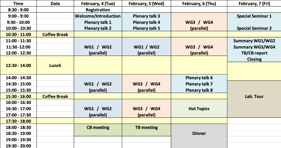
General time table
Location of rooms
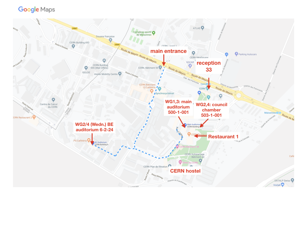 lunch is not organised but can be taken at the CERN restaurant
Adrien Bouygues
Akihiro Kikuchi
Akira Miyazaki
Akira Yamamoto
Alan Wheelhouse
Alban Sublet
Aleksandra Bartkowska
Alexander Navitski
Alexander Romanenko
Alexey Ermakov
Alick Macpherson
Ambra Gresele
Andrew Burrill
Andrew May
Anne-Marie Valente-Feliciano
Anton Ivanov
Antti Vaaranta
Arely Cano
ari palczewski
Bertrand Baudouy
Bhagat-Taaj Sian
Bianca Giaccone
Carlo Pagani
Catherine MADEC
Chao Dong
Charles Reece
chen luo
Christian ARCAMBAL
Claire Antoine
Claude Marchand
Claude Van Daele
Cristian Pira
Dan Gonnella
Daniel Bafia
Daniel Trompetter
Daniel Turner
Dariusz Bocian
David Longuevergne
David Smekens
Denis Kostin
Detlef Reschke
Dirk Lützenkirchen-Hecht
Dorothea Fonnesu
Douglas Holmes
Edward Thoeng
Eiji Kako
Emmy Sharples
Enrico Cenni
Eric Montesinos
Erk JENSEN
Fabien EOZENOU
Fabio Avino
Franck Peauger
Frank Gerigk
Gerda Neyens
Giovanna Vandoni
Grigory Eremeev
Guillaume Devanz
Guillaume Rosaz
Hans Weise
Hao Guo
Hassen JENHANI
Hiroaki Umezawa
Hiroki Okuno
Hiroshi Sakai
Hongtao Hou
James Mitchell
Jan-Hendrik Thie
jean-pierre Pollina
Jens Iversen
Joern Schaffran
Jonas Christian Wolff
Jonathan Angle
Julien Branlard
Juliette Plouin
Karol Kasprzak
Katarzyna Turaj
Katherine Wilson
Kazunari Yamada
Kazutaka Ozeki
Keitaro Kondo
Kellen McGee
Kenji Suda
Kensei Umemori
Kevin Smith
Kyle Branigan
Laura Monaco
Laura Popielarski
Lea Steder
Leonel Ferreira
Lorena Vega Cid
Lucia Lain Amador
Lukasz Piotr Krzempek
Manfred Tonutti
Marc Wenskat
Marco Garlasche
Mark Pendleton
Martina Martinello
Marton Major
Masao Irikura
Massamba Diop
Mateusz Wiencek
Mattia Checchin
Mauro Taborelli
Michael Kelly
Michele Bertucci
Mircea Stirbet
Mohammed Fouaidy
Myeun Kwon
Naruhiko Sakamoto
Nicholas Shipman
Nicholas Walker
Nicolas BAZIN
Nuno Elias
Nuria Valverde Alonso
Ofelia Capatina
Oliver Kugeler
olivier brunner
Olivier Napoly
Paolo Chiggiato
paolo pierini
Pashupati Dhakal
Patricia Duchesne
Paul Smith
Paulina Kulyavtsev
Peng Sha
Peter McIntosh
Peter Oving
Phil Atkinson
Philipp Kolb
Purushottam Shrivastava
Qiong Wu
Ram Dhuley
Rama Calaga
Ricardo Monroy-Villa
Riccardo Zennaro
Richard Stanek
Robert Laxdal
Robert Nietubyc
Robert Rimmer
Robert Zierold
Robin FERDINAND
Roger Ruber
Romain Gerard
Rong-Li Geng
Ryan Porter
Said Atieh
Sam Posen
Sangbeen Lee
Sanghoon Kim
Sebastian Aderhold
Sebastian Keckert
Sergey Belomestnykh
Sergio Calatroni
Serhan Tufanli
Shin MICHIZONO
Shreyas Balachandran
Silvia Verdú-Andrés
Silvia Zorzetti
Stephen Einarson
Steven Anlage
Stéphane BERRY
Stéphane Bethuys
Stéphanie Fernandez
Suitbert Ramberger
Sven Sievers
Takashi Ebisawa
Takeshi Dohmae
Teng Tan
Thibaut Richard
Thomas Proslier
Tobias Junginger
Tom Powers
Tongming Huang
Torsten Koettig
Tug Arkan
Valentin Gerbet
Vanessa Garcia Diaz
Walter Venturini Delsolaro
WENCAN XU
Wolf-Dietrich Moeller
Wolfgang Hees
Yasuchika Yamamoto
Yuefeng Liu
Yuriy Pischalnikov
Zachary Conway
Zeming Sun
-
-
08:15
→
09:00
On-site Registration 45m 500/1-001 - Main Auditorium
-
09:00
→
10:30
Plenary: Welcome, Plenary talk 1, Plenary talk 2 500/1-001 - Main Auditorium
Welcome, Plenary talk 1, Plenary talk 2
Conveners: Frank Gerigk (CERN), Robert Edward Laxdal-
09:00
CERN welcome and logistics 15mSpeakers: Frank Gerigk (CERN), Sergio Calatroni (CERN)
-
09:15
Introduction and update from last collaboration meeting 15mSpeaker: Hans Weise (DESY)
- 09:30
-
10:00
High-Q/High-G TTC task force report 30mSpeaker: Martina Martinello (Fermilab - IIT)
-
09:00
-
10:30
→
11:00
Coffee Break 30m 500/1-001 - Main Auditorium
-
11:00
→
12:30
Working Group Session: WG1 _Low/Mid T Bakes + N-treatments 500/1-001 - Main AuditoriumConveners: Ari Palczewski (JLAB), Dr Kensei Umemori (KEK), Marc Wenskat (Deutsches Elektronen-Synchrotron DESY)
-
11:00
New results of KEK infusion and mid-T bake 15mSpeaker: Kensei Umemori (KEK)
-
11:15
Update on insitu mid-T bake 15mSpeaker: Sam Posen (FNAL)
- 11:30
-
11:45
High Q&G activity at IHEP 15mSpeaker: Chao Dong (IHEP)
-
12:00
Status of infusion studies at IJCLab/CEA-Saclay 15mSpeaker: David Longuevergne (IPNO)
-
12:15
Status of infusion studies at JLab 15mSpeaker: Pashupati Dhakal (Jefferson Lab)
-
11:00
-
11:00
→
12:30
Working Group Session: WG2_Couplers and Auxiliaries 503/1-001 - Council ChamberConveners: Eric Montesinos (CERN), Naruhiko Sakamoto (RIKEN), Sang Hoon Kim (FRIB)
-
11:00
Fundamental studies for power coupler in KEK (10'+8') 18m
Abstract:
KEK is concentrating on studies of copper plating and ceramic from 2016. Recently, in study of copper plating, it became clear that copper-sulfate is much better than copper-pyrophosphate by analysis of RRR and grain size for each. On the other hand, KEK constructed measurement system of secondary electron emission for ceramic, and have been measured many samples provided from five vendors including TiN and Cr2O3 coating. In this talk, these results will be presented, and discussed.Provocative topic:
Copper plating by sulfate and pyrophosphate, secondary electron emission of ceramic incl. coatingSpeaker: Yasuchika Yamamoto (KEK) -
11:18
R&D Toward a 500 kW CW High Power Coupler with Variable Qext (10'+8') 18m
Abstract:
The SRF cavities for the electron storage ring of an Electron-Ion Collider (EIC) to be built at BNL require CW high power couplers with variable Qext. The approach taken to develop this coupler was to leverage an existing 500 kW CW fixed coupler design, and implement the coupling adjustment by means of a waveguide tuner section adjacent to the coupler. This talk will briefly present the R&D approach and progress to date including design choices, fabrication and results of the initial high power testing of the couplers which were recently completed, and plans of high power couplers for BNL EIC applications.Provocative Topics:
High power coupler adjustment via waveguide tuner with a fixed coupler; challenging performance requirements for the BNL EIC electron storage ring SRF system; high power test results with lessons learned and plan moving forward.Speaker: Wencan Xu -
11:36
Qext studies for the 1.5 GHz BESSY VSR couplers (10'+8') 18m
Abstract:
The 1.5 GHz couplers for the high-current CW variable pulse-length demonstrator in BESSY II, are now out in the process of being manufactured. These couplers are designed to provide variable coupling, with the initial design brief that their Qext range was from 6x10⁶ to 6x10⁷. Through the process of design development it was found that a full order of magnitude range could not be reached. In this talk, the reason behind the reduced range is discussed and studies are presented detailing how the final coupling range was chosen. Since the couplers do not exist on their own but as part of a larger system, the external effects on the Qext as a result of mechanical constraints in the module will also be presented, to show how the full system is interlinked.Provocative topics:
That is an interesting term. Essentially, how mechanical constraints from the overall SRF system, have more effect on the design than the RF, however I am not sure whether that is provocative or new to anyone who designs couplers.Speaker: Emmy Sharples -
11:54
Our experiences and troubles on FPCs for RIKEN QWR (10'+8') 18m
Abstract:
In RIKEN, ten QWRs and ten FPCs were produced.
The rinsings and RF processes for ten FPCs seemed to have finished without any trouble.
Three CMs were assembled and installed on the beam line.
After about two months of evacuation of CMs, a leakage from vacuum window broke out at one of the FPCs.
Because a basal treatment is difficult, we evacuate the FPC from air side of the window to perform excitation test of QWRs.
The effects of leakage on other QWRs in same CM are being examined.
A couse of leakage is unspecified for now.Speaker: Kazutaka Ozeki (RIKEN) -
12:12
Special design considerations of high power input couplers for TEM-type superconducting cavities (10'+8') 18m
Abstract:
High power input couplers of TEM-type superconducting cavities (QWR, HWR, Spoke) usually locate at the cavity body instead of beam pipe, which requests special design considerations in addition to the conventional design criteria. Firstly, the ceramic window may be damaged by field emission (FE) induced electrons. Thus it’s important to ensure no FE electrons can arrive at the ceramic surface by either optimizing the window position or blocking the electrons with specially designed shielding. Secondly, the cavity field will leak into the coupler and cause excessive heating, which may result in substantial dynamic heat load, even cavity quench. Therefore dedicated rf-thermal simulation should be done to reduce the filed leakage by optimizing the coupler position and the height of the coupler port. In addition, compact design to realize clean assembly and to minimize the contamination will be discussed.Speaker: Tongming Huang (IHEP)
-
11:00
-
12:30
→
14:00
Lunch 1h 30m
-
14:00
→
15:30
Working Group Session: WG1_Low/Mid T Bakes + N-treatments 500/1-001 - Main AuditoriumConveners: Ari Palczewski (Thomas Jefferson National Accelerator Facility), Kensei Umemori (KEK), Marc Wenskat (Deutsches Elektronen-Synchrotron DESY)
-
14:00
Progress in N doping at FNAL – new developments in higher gradients insights 18mSpeaker: Daniel Bafia (Fermi National Accelerator Laboratory)
-
14:18
LCLS-II investigation of failed LCLS-II HE prototype cavities EP analysis 18mSpeaker: Dr Mattia Checchin (FNAL)
-
14:36
Test results from the TRIUMF multi-mode coaxial resonators 18mSpeaker: Philipp Kolb (TRIUMF)
-
14:54
New low-T sample studies highlighting the important role of oxygen diffusion 24mSpeaker: Alexander Romanenko (Fermilab)
-
15:18
Sample Survey - Presentation 12m
-
14:00
-
14:00
→
15:30
Working Group Session: WG2_Couplers and Auxiliaries 503/1-001 - Council ChamberConveners: Eric Montesinos (CERN), Naruhiko Sakamoto (RIKEN), Sang Hoon Kim (FRIB)
-
14:00
Update on FPC progress at DESY (10'+8') 18m
ABSTRACT
A Fundamental Power Coupler (FPC) is one of the key subsystems of the SRF accelerator and does need to be addressed in same way, as the SRF cavities are. Currently most of the FPCs for the SRF cavities at DESY are installed in the Eu-XFEL linac (~800), but this is not the only application. The FLASH linac will undergo the update soon
and CW operation of an SRF accelerator is under study. We plan also a refresh of our SRF testing facility with a new FPC test-stand.
All these topics will be presented in short and discussed.Provocative topics:
1. CW module test - how far can a standart E-XFEL module be used with CW operation - limits/problems
2. Coupler test for FPC intended for CW operation - is it needed ? lower voltages with higher DF...Speaker: Denis Kostin (DESY) -
14:18
Experience with FPCs for the LCLS-II project at JLAB (10'+8') 18m
Abstract:
The LCLS II project make used of use of state of the art superconducting cryo-modules RF powered in CW mode by dedicated TTF3 style FPCs. The talk will provide details related with LCLS-II cryo-module production experience at JLAB using this type of couplers.Provocative topic:
The modified TTF3 is a complex coupler, I wished it was simpler. Will this coupler demonstrate similar performances as we had on power couplers sustaining operation on LEP, LHC or SNS machines?Speaker: Mircea Stirbet (Jefferson Laboratory) -
14:36
Test bench conditioning of the ESS couplers for elliptical cavities (10'+8') 18m
Abstract:
After a short presentation of the architecture and features of the ESS couplers used with elliptical cavities, we will present how we perform the conditioning of the couplers at CEA Saclay and the different diagnostic elements used to check the correct working of the couplers. We will discuss on the consequences of a “bad” TiN coating on the coupler performances during the conditioning.Provocative topics:
Do we install too many diagnostic elements on the couplers during the conditioning?Speaker: Christian Arcambal (CEA) -
14:54
High power testing of ESS FPCs on the elliptical cavities cryomodules (10'+8') 18m
Abstract:
We discuss the behavior of the 1.2 MW power couplers on the ESS medium beta elliptical cavities cryomodule during high power test in the Saclay test bunker. We go through three test conditions, room temperature, cold with detuned cavity and with the nominal case of tuned cavities at 2 Kelvin.Provocative topic:
Do we condition FPC enough?Speaker: Guillaume Devanz (CEA) -
15:12
Technical Issues on RF power coupler for QWR and HWR cavity in RISP (10' + 8') 18m
Abstract
RF power couplers for QWR and HWR cavity are under the mass production in RISP. We will present the technical issues which occurred during the preparation and test of the RF power couplers. The contamination of the coupler is occurred after the ultra-sonic cleaning (USC) with the DI-water. The USC procedure of the coupler is modified as replacing the DI-water to the ethanol. The material for metallization of ceramic window, which is AgCu alloy (Ag-50% Cu-50%), could be oxidized by the DI-water. And the surface of the outer conductor is contaminated after the USC procedure. Substitute the ethanol for the DI-water, the contamination of ceramic window is not observed after the USC procedure. Also, the decay time measured from the RF power coupler has non-linearity when the RF power switched off. This non-linearity of decay time is only observed in horizontal test. The non-linearity of decay time makes the decay time longer than the linear decay time, and the loaded Q is also increased. The linear part of the decay time, which is a few hundreds of micro-second after the RF power switched off, is used for calculation of the loaded Q.Provocative topics:
The high pressure rinse procedure is necessary for clean room preparation of RF power coupler?
The reason of the non-linearity in the measured decay timeSpeaker: Sangbeen Lee (Institute for Basic Science)
-
14:00
-
15:30
→
16:00
Coffee Break 30m 500/1-001 - Main Auditorium
-
16:00
→
17:30
Working Group Session: WG1_Sample Studies 500/1-001 - Main AuditoriumConveners: Ari Palczewski (Thomas Jefferson National Accelerator Facility), Kensei Umemori (KEK), Marc Wenskat (Deutsches Elektronen-Synchrotron DESY)
-
16:00
Sample Survey - Discussion 18m
-
16:18
New insights on the SRF Nb cavities performance from spectroscopic data. An XPS study 18mSpeaker: Arely Cano (FNAL)
-
16:36
In-Situ EXAFS Investigation of N2 treatment of Nb 18mSpeaker: Dirk Lützenkirchen-Hecht (U Wuppertal)
-
16:54
The challenges of fully calibrated SIMS measurements using ion implant standards 18mSpeaker: Jonny Angle (Jlab/Virginia Tech)
-
17:12
Sample Studies on Nitrogen- and Heat-Treatments of Niobium 18mSpeaker: Marc Wenskat (Deutsches Elektronen-Synchrotron DESY)
-
16:00
-
16:00
→
17:30
Working Group Session: WG2_Couplers and Auxiliaries 503/1-001 - Council ChamberConveners: Eric Montesinos (CERN), Naruhiko Sakamoto (RIKEN), Sang Hoon Kim (FRIB)
-
16:00
R&D Toward High Power Warm SiC Beam Line HOM Absorbers (10' + 8') 18m
Abstract:
The SRF cavities for the electron storage ring of an Electron-Ion Collider (EIC) to be built at BNL are planned to operate continuous wave (CW) with beam currents ranging from 0.26 to 2.5A and energies from 5 to 18 GeV. Strong High Order Mode (HOM) damping is necessary to maintain beam stability. Our approach is to use Silicone Carbide (SiC) as a lossy dielectric located in the room-temperature beamlines adjacent to the SRF cavities to absorb the HOM power. Simulations predict up to 80 kW of CW HOM power per cavity during operation. This talk will briefly present plans and analysis to extract the HOM power from the SiC material into a water-cooled section of beampipe along with progress to date on the prototype fabrication of the Beam Line Absorbers (BLAs). Plans for low power and high power testing will also be presented.Provocative Topics:
Beampipe vs waveguide or coaxial HOM coupling, very high HOM power absorbers, SRF cavity contamination from SiC particulate.Speaker: Doug Holmes (BNL) -
16:18
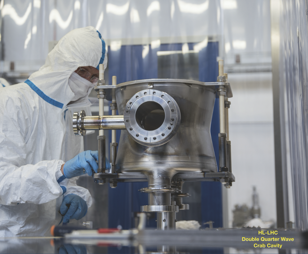
HOM couplers for crab cavities and challenges (10'+8') 18m
Abstract:
Two types of crab cavities will be installed into the LHC as part of the HL-LHC project. To mitigate the problems of large beam-induced heat-loads and instabilities, the higher order modes in both cavities are damped by coaxial couplers. This presentation will detail the HOM damping mechanisms chosen, specifically looking into broad-band damping and limitations with dynamic heat loads. Finally, design constraints arising from manufacture and transport are presented with key points for discussion.Provocative topics:
High power SC HOM couplers, gasket heat loads, transport of HOM couplers, manufacture of HOM couplers.Speaker: James Alexander Mitchell (CERN) -
16:36
Newest Piezo-Actuators for High Dynamic Rate Operation (10'+8') 18m
Abstract:
To compensate for SRF cavity Lorentz Force Detuning fast/piezo actuator must operate at high amplitude and high dynamic rate. The piezo-actuator when operated inside insulate vacuum environment with pulses of large amplitude could be overheated quickly. Uncontrollable increase of the piezo actuator temperature could lead to the failure of the actuator, as reported in many papers.
Removing heat from piezo-ceramic when it is operated inside insulate vacuum environment complicated task that newer addressed previously. FNAL and PI team developed newest high dynamic rate (HDR) piezo-ceramic actuator that has unique way to remove heat from piezo.
Design of the newest actuator-actuators and preliminary test results will be presented.
This new HDR piezo-actuators could significantly increase reliability of the fast tuners for compensation of Lorentz Force detuning in the SRF Linacs that operated in RF-pulse mode.Provocative topic:
What is reliability/ longevity of the piezo-tuners that deployed in recent SRF linacs?
What are the reasons that practically every modern SRF accelerator system that built recently has piezo-tuners?
But not many facility is running piezo-actuators 24/7 ?
Low reliability of the piezo? And the risk that piezo-stack could fail prevent it from
actively operate fast/piezo tuners for High Dynamic Rate operation?Speaker: Yuriy Pischalnikov (FERMILAB) -
16:54
Compact tuner designed to minimize the intervals of QWRs for RIKEN heavy-ion linac (10'+8') 18m
Abstract:
The superconducting booster linac at RIKEN (SRILAC) has ten 73-MHz quarter-wavelength resonators (QWRs) that are contained in three cryomodules (CMs).
Focusing element of quadrupole magnets at room temperature were installed between CMs. In order to obtain optimum beam dynamics, an intervals of QWRs was set as small as 110 mm. Frequency tuning during cold operation is performed by compressing the beam port of the cavity and decreasing the length of each beam gap using a dynamic tuner. The tuning range of the cavity itself is from 0 to -14 kHz. The tuner is used to tune by a few kHz at the beginning of the cavity excitation, and by a few Hz for a long term operation in order to compensate the frequency change by helium pressure.
Since the intervals of QWRs is small, a compact design of the dynamic tuner was adopted. The support plates were welded to the helium jacket, and surrounding wires were attached.
A cavity frequency is decreased by tightening the wires, which is driven by a stepping motor and gears (ratio is 1:64).
In a cooling test at 4K, each cavity was successfully tuned to the design frequency by the tuner, in which the required frequency change was 3 kHz to 8 kHz depending on the cavity.
There is a hysteresis of around 10 Hz, which is caused by a backlash of the mechanical system.
The sensitivity of helium pressure was estimated to be df/dp = -1.91 Hz/hPa by a 3D EM calculation. In a short term (in periods of 2--3 minutes), helium pressure is stable by around 4 hPa (8 Hz) against the bandwidth of 50 Hz. Long term stability test (1 day) is underway.
If the frequency is not stable enough, an automatic frequency tuning will be necessary.
The tuner design and test results with cold cavities will be presented.Provocative topics:
Compact tuner for QWR, minimal interval of QWR
Performance test of tunerSpeaker: Kenji Suda (RIKEN) -
17:12
Resonance control with pneumatic slow frequency tuners for FRIB > half-wave resonators (10' + 8') 18m
Provocative topics:
Mechanical modes integrated with a pneumatic tuner, magnetic hygiene with a pneumatic tuner, use of 'industrial-class' proportional solenoid valves for large-scale SRF acceleratorsSpeakers: John Popielarski (FRIB), Sang Hoon Kim (FRIB)
-
16:00
-
17:30
→
18:00
Break 30m 500/1-001 - Main Auditorium
-
18:00
→
19:00
-
08:15
→
09:00
-
-
09:00
→
10:30
Plenary: Plenary talk 3, Plenary talk 4, Plenary talk 5 500/1-001 - Main Auditorium
Welcome, Plenary talk 1, Plenary talk 2
Convener: Wolf-Dietrich Moeller (DESY)-
09:00
Statistical Analyses of Nitrogen-Doped Cavity Production for LCLS-II Cavities 30mSpeaker: Dan Gonnella (SLAC)
-
09:30
Spiral 2 SRF commissioning 30mSpeaker: Robin Ferdinand (GANIL)
-
10:00
Workshop Report from ERL2019 at HZB 30mSpeaker: Peter Mcintosh
-
09:00
-
10:30
→
11:00
Coffee Break 30m 500/1-001 - Main Auditorium
-
11:00
→
12:30
Working Group Session: WG1_Flux Expulsion 500/1-001 - Main AuditoriumConveners: Ari Palczewski (Thomas Jefferson National Accelerator Facility), Kensei Umemori (KEK), Marc Wenskat (Deutsches Elektronen-Synchrotron DESY)
-
11:00
Flux expulsion measurement with a flux lens 18mSpeaker: Anton Evgeniev Ivanov (CERN)
-
11:18
Metallurgical approach to addressing the issue of flux-trapping in Nb cavities and the variability found when using Nb sheet from different sources 18mSpeaker: Shreyas Balachandran (NATIONAL HIGH MAGNETIC FIELD LAB)
-
11:36
Comparison for the vortex penetration and dynamics in Nb, Nb/N and NbTi plates 18mSpeakers: Chao Dong (IHEP), Haihu Wen (Nanjing U)
-
11:54
Flux expulsion on small samples for LCLS-II HE 18mSpeaker: Paulina Kulyavtsev
-
12:12
Material studies on High-T Doping 18mSpeaker: Marton Major (TUDA)
-
11:00
-
11:00
→
12:30
Working Group Session: WG2_Couplers and Auxiliaries 6/2-024 - BE Auditorium MeyrinConveners: Eric Montesinos (CERN), Naruhiko Sakamoto (RIKEN), Sang Hoon Kim (FRIB)
-
11:00
Power Couplers - Technology, manufacturing, and four ways to procure for half the price (15' + 8') 23m
Abstract:
Power couplers provide the vacuum and thermal interface between the superconducting cavity and the room temperature waveguide components, and transmit microwave power. The production of Power Couplers require a unique set of manufacturing processes. Procurement costs can vary widely for a number of reasons. This paper will show the critical technologies required and the breakdown of major components of cost.Provocative topic:
Four methods to procure couplers for half the price will be discussed, along with recommendations for cost savings from a manufacturers perspective.Speaker: Steve Einarson (CPII) -
11:23
THALES experience for EU-XFEL project – From the (non)pre-industrialization phase to mass production (15'+8') 23m
Abstract:
In July 2010, THALES Electron Devices (now THALES Avionics France SAS) in consortium with Research Instrument has be awarded by CNRS/IN2P3 for the mass production of 670 RF couplers at 1.3GHz for the EU-XFEL project in Hamburg. This positive outcome has been the result of a long journey started in 2004 by several steps of consultation and discussions between the laboratories acting as design authorities / in-kind contributors to the project and the Industry.Provocative topic:
In this talk, we will summarize the pre-tendering discussions and the aborted industrialization phase seen from THALES stand point and the consequences during project successful execution from 2010 till 2015.Speaker: Stephane Bethuys (THALES) -
11:46
Development of fundamental power couplers for several years at CETD (15' + 8') 23m
Abstract:
CETD (former company name: TETD) has developed and manufactured FPCs since more than 30 years ago in collaboration with KEK or other research institutes.
Recent years we succeeded in contract with overseas customers and we made efforts to solve various problems in order to satisfy customers requirements.
In this talk, our products developed in last few years will be introduced and some proposals and requests from the supply side will be presented.Speaker: Masao Irikura (CANON) -
12:09
Remarks on the industrial production of FPC (15' + 8') 21m
Abstract:
The talk will address the positive and negative experiences that RI gained during the production of FPC in large scale series (E-XFEL, LCLS-II) and small scale projects. The most critical processes and head-aches will be reflected from “behind the scenes”.
The specifications do often cut the edge of achievable copper plating, TIN deposition and mechanical tolerances in a serial production and sometimes seem to be overshooting. The current development from pulsed to CW machines does raise the question, if the TTF-III coupler as a design baseline is still up to date.Provocative topics:
Overtight copper plating specifications
TIN deposition control (nanometers!)
Specified mechanical tolerances
Is the TTF-III coupler still up to date?Speaker: Daniel Trompetter (RI Research Instruments GmbH)
-
11:00
-
12:30
→
14:00
Lunch 1h 30m
-
14:00
→
15:30
Working Group Session: WG3_Coating techniques 500/1-001 - Main AuditoriumConveners: Guillaume Jonathan Rosaz (CERN), Teng Tan (IMP), Tobias Junginger (University of Victoria/TRIUMF)
-
14:00
Development of coating system for the Wide Open Waveguide (WOW) Crab Cavity (10'+8') 18mSpeaker: Fabio Avino (CERN)
-
14:18
Progresses on ECR plasma deposited Nb thin films (10'+8') 18mSpeaker: Anne-Marie Valente-Feliciano (Jefferson Lab)
- 14:36
-
14:54
Test results of re-built LHC spare cavities (10'+8') 18mSpeaker: Mr Franck Peauger (CERN)
-
15:12
ARIES WP15 progresses (10'+8') 18mSpeaker: Oliver Julius Kugeler
-
14:00
-
14:00
→
15:30
Working Group Session: WG4_New Fabrication Methods (1 /2) 6/2-024 - BE Auditorium MeyrinConveners: Hiroshi Sakai (KEK), Stephane Berry (CEA), Tug Arkan (FNAL)
-
14:00
Seamless cavities via electrodeposition 15mSpeaker: Lucia Lain Amador (CERN)
-
14:15
Developments of Niobium atomize powder for superconducting 15mSpeaker: Takeshi Dohmae (KEK)
-
14:30
Metal Additive Manufacturing at CERN in general and SRF Niobium 15mSpeaker: Romain Gerard
-
14:45
Electron beam welding for cavity production, collaboration with KEK on internal welding of 1.3GHz type cavities 15mSpeaker: Peter Oving (TECHMETA Company)
-
15:00
Novel Technologies applied to SRF (cavity) fabrication 15mSpeaker: Said Atieh (CERN)
-
15:15
Fabrication Experience with Balloon SSR Cavity at TRIUMF 15mSpeaker: Robert Edward Laxdal
-
14:00
-
15:30
→
16:00
Coffee Break 30m 500/1-001 - Main Auditorium
-
16:00
→
17:30
Working Group Session: WG3_Alternative Materials/Structures to Nb films 500/1-001 - Main AuditoriumConveners: Guillaume Jonathan Rosaz (CERN), Teng Tan (IMP), Tobias Junginger (University of Victoria/TRIUMF)
-
16:00
Recent SIS layer results (10'+8') 18mSpeaker: Claire Antoine (CEA)
-
16:18
Overview Multilayers RF results (10'+8') 18mSpeaker: Sebastian Keckert (Helmholtz-Zentrum Berlin)
- 16:36
-
16:54
Two-stage coating of MgB2 system (10'+8') 18mSpeaker: Hiroshi Sakai (KEK)
-
17:12
CVD Thick Nb film and cavity coating (10'+8') 18mSpeaker: Zeming Sun (Cornell)
-
16:00
-
16:00
→
17:30
Working Group Session: WG4_New Fabrication Methods (2 /2) and Alternative Cooling Techniques 6/2-024 - BE Auditorium MeyrinConveners: Hiroshi Sakai (KEK), Stéphane BERRY (CEA-Saclay), Tug Arkan (FNAL)
-
16:00
RFD crab cavities manufacturing experience at CERN 15mSpeaker: Marco Garlasche (CERN)
-
16:15
Methods and results of laser welding of niobium 15mSpeaker: Kyle Branigan (II-IV)
-
16:30
Stand-Alone Cryocooler-Based Module for the ATLAS Multi-User Upgrade 15mSpeaker: Michael Kelly (ANL)
-
16:45
An effective thermal link for cooling cryo-magnetic systems : The Pulsating Heat Pipe (PHP) 15mSpeaker: Dr Bertrand Baudouy (CEA Paris-Saclay)
-
17:00
Developing conduction-cooled SRF cavities and first test results 15mSpeaker: Dr Ram Dhuley (Fermi National Accelerator Laboratory)
-
17:15
Results from a multi-metallic conduction-cooled SRF single-cell cavity 15mSpeaker: Robert Alan Rimmer
-
16:00
-
17:30
→
18:00
Break 30m 500/1-001 - Main Auditorium
-
18:00
→
19:00
-
09:00
→
10:30
-
-
09:00
→
10:30
Working Group Session: WG3_Progress on Nb3Sn towards accelerator 500/1-001 - Main AuditoriumConveners: Guillaume Jonathan Rosaz (CERN), Teng Tan (IMP), Tobias Junginger (University of Victoria/TRIUMF)
-
09:00
Nb3Sn progressess from Cornell (10'+8') 18mSpeaker: Ryan Porter (CLASSE)
-
09:18
Nb3Sn coated 1.5 GHz multi-cell cavities and perspectives for beam acceleration tests (10'+8') 18mSpeaker: Grigory Eremeev (FNAL)
-
09:36
Advances in Nb3Sn coating at Fermilab including recent world-record performance cavity results (10'+8') 18mSpeaker: Mr Sam Posen (FNAL)
-
09:54
Nb3Sn thin film synthesized via bronze route (10'+8') 18mSpeaker: Akihiro Kikuchi (National Institute for Materials Science)
-
10:12
Nb3Sn from the lab to the machine (10'+8') 18mSpeaker: Rama Calaga (CERN)
-
09:00
-
09:00
→
10:30
Working Group Session: WG4_Non standard concepts 503/1-001 - Council ChamberConveners: Hiroshi Sakai (KEK), Stéphane BERRY (CEA-Saclay), Tug Arkan (FNAL)
-
09:00
Measurement results of moving particles during STF cryomodule assembly under slow pumping/venting in KEK (12/20) 15mSpeaker: Hiroshi Sakai (KEK)
-
09:15
IFMIF/QST on dust particle measurements by using "a vacuum particle counter" 15mSpeaker: Takashi Ebisawa (QST)
-
09:30
Cryomodule design, assembly and installation utilizing “KOACH” system 15mSpeaker: Nari Yamada (RIKEN)
-
09:45
plasma processing and particulate's composition 15mSpeaker: Bianca Giaccone (Fermilab)
-
10:00
Development of the position monitor by white light interferometer method in cryomodule at cERL 15mSpeaker: Hiroshi Sakai (KEK)
-
10:15
Computer Vision solutions for Robot-assisted technology in SRF assembly at Fermilab 15mSpeaker: Silvia Zorzetti (FNAL)
-
09:00
-
10:30
→
11:00
Coffee Break 30m 500/1-001 - Main Auditorium
-
11:00
→
12:30
Working Group Session: WG3_Characterization techniques 500/1-001 - Main AuditoriumConveners: Guillaume Jonathan Rosaz (CERN), Teng Tan (IMP), Tobias Junginger (University of Victoria/TRIUMF)
-
11:00
HIPIMS from QPR to 1.3GHz cavities (10'+8') 18mSpeaker: Lorena Vega Cid (Centro de Investigaciones Energéti cas Medioambientales y Tecno)
-
11:18
Predicting SRF Performance using muSR and betaNMR (10'+8') 18mSpeaker: Edward Thoeng
-
11:36
RF local magnetometry (10'+8') 18mSpeaker: Steven Anlage (UMD)
-
11:54
Predicting SRF performance PCT (10'+8') 18mSpeaker: Thomas Proslier (CEA)
- 12:12
-
11:00
-
11:00
→
12:45
Working Group Session: WG4_Robotic Techniques 503/1-001 - Council ChamberConveners: Hiroshi Sakai (KEK), Stéphane BERRY (CEA-Saclay), Tug Arkan (FNAL)
-
11:00
Robotics HPR Application for Elliptical FRIB Upgrade Cavity 15mSpeaker: Laura Popielarski (FRIB/MSU)
-
11:15
Robot assisted cavity HPR and assembly at IMP 15mSpeakers: Hao GUO (IMP), Teng Tan (IMP)
-
11:30
Remote handling of UHV beam pipe connections in high-radiation zones 15mSpeaker: Lukasz Piotr Krzempek (CERN)
-
11:45
Robotic disk stacking for the production of RF structures 15mSpeaker: Riccardo Zennaro (PSI)
-
12:00
Chemical & Electropolishing facility for niobium (HL-LHC) and copper (FCC) substrates 15mSpeaker: Valentin Gerbet
-
12:15
Seeking for a novel fabrication technology large-bore SRF-QWR cavity for 1-ampare class linac 15mSpeaker: Hiroki Okuno (RIKEN)
-
11:00
-
12:30
→
14:00
Lunch 1h 30m
-
14:00
→
15:30
Plenary: Plenary talk 6, Plenary talk 7, Plenary talk 8 500/1-001 - Main Auditorium
Welcome, Plenary talk 1, Plenary talk 2
Convener: Eiji Kako (KEK)- 14:00
-
14:30
Technical challenges for Korean SC Heavy Ion Accelerator 30mSpeaker: Myeum Kwon (RISP)
-
15:00
Indian SRF contribution for FNAL PIP-II project 30mSpeaker: Purushottam Shrivastava (RRCAT)
-
15:30
→
16:00
Coffee Break 30m 500/1-001 - Main Auditorium
-
16:00
→
17:30
Hot Topic: Processing and testing of large elliptical cavities (<1 GHz) for hadron linacs 500/1-001 - Main AuditoriumConveners: Grigory Eremeev (FNAL), Paolo Pierini (ESS), Sha Peng (IHEP)
-
19:00
→
21:00
Dinner Edelweiss
Edelweiss
-
09:00
→
10:30
-
-
09:00
→
10:30
Plenary: Special Seminar 1, Special Seminar 2 500/1-001 - Main Auditorium
Welcome, Plenary talk 1, Plenary talk 2
Convener: Sergey Belomestnykh (Fermilab)-
09:00
Nuclear Reactions Studies with Radioactive Ion Beams at HIE-ISOLDE 45mSpeaker: Gerda Neyens (CERN)
-
09:45
Physics and technology overview of LBNF Dune 45mSpeaker: Serhan Tufanli (CERN)
-
09:00
-
10:30
→
11:00
Coffee Break 30m 500/1-001 - Main Auditorium
-
11:00
→
13:00
Plenary: Summary WG1, WG2, WG3, WG4, TB/TC report, closing 500/1-001 - Main Auditorium
Welcome, Plenary talk 1, Plenary talk 2
Convener: Paolo Pierini (ESS)-
11:00
WG1 Report 15mSpeakers: Ari Palczewski (Thomas Jefferson National Accelerator Facility), Kensei Umemori (KEK), Marc Wenskat (Deutsches Elektronen-Synchrotron DESY)
-
11:15
WG2 Report 15mSpeakers: Eric Montesinos (CERN), Naruhiko Sakamoto (RIKEN), Sang Hoon Kim (FRIB)
-
11:30
WG3 Report 15mSpeakers: Guillaume Jonathan Rosaz (CERN), Teng Tan (IMP), Tobias Junginger (University of Victoria/TRIUMF)
-
11:45
WG4 Report 15mSpeakers: Hiroshi Sakai (KEK), Stéphane BERRY (CEA-Saclay), Tug Arkan (FNAL)
-
12:00
Technical Board Report 15mSpeaker: Eiji Kako (KEK)
- 12:15
-
12:30
Closing Remarks 15m
-
11:00
-
13:00
→
14:15
Lunch 1h 15m
-
14:15
→
16:00
Lab. Tour
-
09:00
→
10:30